Key Design Principles in Pneumatic Conveying Pipework: Bends, Velocity, Wear Points & Pressure Drop
Designing efficient pneumatic conveying pipework is one of the most critical aspects of any bulk material handling system. Whether you are transporting powders, pellets, grains, or granular materials, the performance of the system depends heavily on how the pipeline is designed.
Poor design leads to excessive wear, blockages, high energy consumption, and inconsistent product flow. On the other hand, a well-engineered system improves reliability, reduces maintenance costs, and extends equipment life.
In this blog, we will explore the key design principles in pneumatic conveying pipework, focusing on four essential areas:
- Pipe bends and routing
- Air velocity control
- Wear points and material erosion
- Pressure drop and system efficiency
Understanding Pneumatic Conveying Systems
Pneumatic conveying uses air pressure or vacuum to transport bulk materials through a sealed pipeline. It is widely used in industries such as:
- Plastics and polymer processing
- Flour, grain, and food production
- Cement and building materials
- Chemical and pharmaceutical manufacturing
- Milling and processing plants
There are two main types of conveying systems:
- Dilute phase conveying – high velocity, low pressure, materials are suspended in air
- Dense phase conveying – low velocity, high pressure, materials move in slugs or plugs
Each system behaves differently, but both rely on carefully designed pipework to operate efficiently.
Pipe Bends: The Most Critical Design Feature
Pipe bends are one of the most overlooked yet most damaging points in pneumatic conveying systems. Every change in direction affects airflow, material momentum, and wear rate.
Why bends matter
When material changes direction, it does not naturally follow the airflow. Instead, particles impact the outer radius of bends at high speed. This creates:
- Severe abrasion on outer bend walls
- Increased turbulence and energy loss
- Risk of material degradation (especially fragile products)
- Higher pressure drop across the system
Best practices for bend design
To minimise issues, engineers should consider:
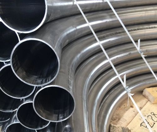
- Large radius bends (3D–10D minimum) to reduce impact force
- Wear-resistant materials such as hardened steel or ceramic-lined bends
- Segmented or replaceable bend sections for easy maintenance
- Gradual directional changes instead of sharp 90° elbows
- Long sweep bends in high-velocity systems
Common mistakes
- Using standard plumbing elbows in industrial conveying lines
- Ignoring product velocity when selecting bend radius
- Failing to account for abrasive materials like flour, silica, or plastic pellets
Even a small improvement in bend design can significantly extend system lifespan.
Air Velocity: Balancing Efficiency and Wear
Air velocity is one of the most important parameters in pneumatic conveying design. It determines whether material moves smoothly or causes excessive wear and system instability.
Too fast vs too slow
- Too high velocity:
- Increases pipe and bend wear
- Breaks fragile materials
- Increases energy consumption
- Creates unnecessary turbulence
- Too low velocity:
- Causes material dropout and blockages
- Leads to inconsistent flow
- Reduces system efficiency
Typical velocity ranges
While values vary depending on material, general guidelines are:
- Fine powders: 15–25 m/s
- Granules and pellets: 18–30 m/s
- Dense phase systems: significantly lower (2–10 m/s equivalent flow behaviour)
Key design considerations
To optimise velocity:
- Maintain consistent pipe diameter throughout the system
- Avoid sudden expansions or contractions
- Match blower capacity to material characteristics
- Use air control valves for fine-tuning system performance
- Consider material bulk density and abrasiveness
Correct velocity selection is often the difference between a stable system and one that constantly blocks or wears out prematurely.
Sources of vibration include:
- Engine harmonics
- Road-induced shock
- Transmission oscillation
- High-frequency mechanical loads
Without proper damping, vibration can cause:
- Fatigue cracking at rigid joints
- Clamp loosening
- Seal failure
- Interface wear
An integrated cooling system must strategically use flexible hose sections to absorb movement and isolate rigid pipework from vibration stress.
Effective vibration control strategies:
- Introducing flexible PTFE hose between rigid pipe runs
- Avoiding over-constrained routing
- Allowing for controlled movement at connection points
- Designing for thermal expansion
- Supporting pipework with appropriate mounting brackets
By designing vibration mitigation into the cooling architecture from the outset, engineers reduce long-term reliability issues.
Wear Points: Identifying and Controlling Erosion
Wear is inevitable in pneumatic conveying systems, but good design can significantly reduce its impact. The key is understanding where wear occurs and why.
High-risk wear locations
The most common wear points include:
- Pipe bends (especially outer radius)
- Feed injection points
- Cyclone separators and filters
- Diverter valves and junctions
- Horizontal-to-vertical transitions
Why wear occurs
Wear is caused by:
- Particle impact at high velocity
- Continuous friction between material and pipe wall
- Abrasive characteristics of the conveyed material
- Turbulence in airflow patterns
Strategies to reduce wear
To extend system life:
- Install wear-back bends or replaceable liners
- Use ceramic or hardened steel pipe sections in high-impact zones
- Reduce velocity where possible without compromising flow
- Design smoother transitions instead of sharp directional changes
- Regularly inspect high-wear areas for early signs of erosion
Material selection matters
Different materials behave differently:
- Plastic pellets: moderate wear but can melt or deform under heat
- Flour and powders: fine abrasion over time
- Glass, sand, and minerals: extremely high wear potential
Selecting the correct pipe material is just as important as the system layout itself.
Pressure Drop: The Hidden Performance Killer
Pressure drop is one of the most critical but least visible issues in pneumatic conveying systems. It directly affects energy consumption, system capacity, and overall performance.
What causes pressure drop?
Pressure loss occurs due to:
- Friction between air and pipe walls
- Direction changes in bends
- Elevation changes (vertical lifts)
- Restrictions in valves or fittings
- Material loading in the air stream
Why it matters
Excessive pressure drop leads to:
- Higher energy costs (larger blowers required)
- Reduced conveying distance
- Lower system efficiency
- Increased risk of blockages
- Reduced material throughput
Design strategies to reduce pressure loss
To optimise pressure performance:
- Minimise the number of bends in the pipeline
- Use smooth internal pipe surfaces
- Avoid unnecessary pipe length
- Design gradual directional changes instead of sharp turns
- Ensure correct pipe diameter for material load rate
Keep filters and separators properly maintained
A well-balanced system ensures that pressure is used to move material, not wasted fighting poor design.
System Integration: Bringing It All Together
The four key factors of bends, velocity, wear points, and pressure drop are all interconnected. Changing one parameter affects the others.
For example:
- Increasing velocity may reduce blockages but increases wear
- Adding bends increases flexibility but raises pressure drop
- Reducing pipe diameter increases velocity but may increase erosion
This is why pneumatic conveying design is never about a single component. It is about system balance.
Key design checklist
When designing or reviewing a system, consider:
- Are bends designed with appropriate radius and wear protection?
- Is air velocity suitable for the material type?
- Have high-wear zones been reinforced or made replaceable?
- Is pressure drop within acceptable operating limits?
- Is the system optimised for long-term maintenance, not just installation cost?
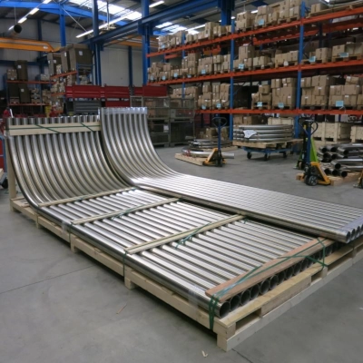
Pneumatic conveying pipework design is a balance of engineering precision and practical experience. Small decisions in layout, velocity selection, and material choice can have a major impact on system performance and lifespan.
By focusing on:
Proper bend design
Controlled air velocity
Strategic wear protection
Minimised pressure drop
You can create a system that is not only efficient but also durable and cost-effective over its operational life.
For industries handling abrasive or high-value materials, investing in good design upfront is always more economical than dealing with breakdowns, maintenance, and inefficiencies later.